ComMarker B4 Galvo Mirror Alignment: Fix Uneven Corners, Weak Corners and Red Dot Offset in Hardware
ComMarker B4 (60W MOPA, JCZ galvo, 110 mm lens) — Hardware Alignment & Calibration Manual
Living document, started 2026-10-18. Machine: Hank-Laptop, LightBurn 1.7.08, field 110x110, centre 55,55, jcz110.cor software correction file. Software (galvo) calibration was completed 2026-10-15: geometry straight. This manual is about the HARDWARE underneath it.
This illustrated manual is for any ComMarker B4 owner searching for: ComMarker B4 galvo mirror alignment, ComMarker B4 red dot not aligned, ComMarker B4 uneven engraving corners, or fiber laser burns weak in corners. Every labelled part in every photograph is also named in real text in the caption below it, so the parts, symptoms and procedures on this page are fully readable and indexable without relying on image-only content.
Quick answer: straight geometry but weak corners means hardware first
If LightBurn software correction makes your burned geometry measure straight, but the burn is still lighter, fatter or weaker in one diagonal pair of corners, do not keep changing software correction, power or speed first. Software correction (scale, skew, trapezoid and bulge, for example the jcz110.cor correction file in LightBurn) straightens geometry. It cannot restore spot size or power density lost when the beam enters the scan lens off-centre and is vignetted (clipped). Straight lines plus diagonal intensity falloff equals a hardware beam-centration problem first, settings second.
If the red-dot pointer is off by about 1 mm but the galvo framing outline is perfect, the red dot is wrong, not the galvo mirrors. The red pointer has its own adjustable mount. Never move galvo mirrors to chase the red dot.
Symptoms that started this (2026-10-18)
- Surface prep (E5 recipe: 25% 1000 mm/s 600 kHz 10 ns, 0.01 interval, crosshatch x2) burned unevenly on a 100x100 plate: top-left and bottom-right corners visibly lighter than the rest; centre solid.
- On the printed calibration card, bottom-, left- and top-right-corner test squares were darkest (asymmetric diagonal pattern).
- Red-dot pointer never lined up with the actual laser burn (~1 mm off), while the framing (galvo outline) laser was perfect.
- Owner history: the X and Y galvo mirrors had previously been moved by hand IN ORDER TO CENTRE THE RED DOT, and the white PVC block clamping the mirror/motor assemblies had been loosened, letting the assemblies also slide IN/OUT accidentally. One motor/mirror was heard to "clip" inside the head while being moved with the targeting laser powered on.
Symptom index: what each pattern usually means
- Diagonal corner falloff — one diagonal pair (for example top-left and bottom-right) is lighter while the opposite diagonal and centre are stronger: suspect off-centre beam entry into the scan lens, vignetting, and a fat, weak spot toward the clipped corners.
- Red dot offset ~1 mm with perfect framing — the galvo framing outline lands correctly but the red-dot pointer is offset from the real infrared burn: suspect the red-dot pointer mount, not the galvo mirrors.
- Weak corners, all four corners equally light — can be normal field falloff at the edge of a 110 mm field; compare against the centre with an identical test square before opening the head.
- One-axis gradient — light-to-dark mainly left-to-right or mainly top-to-bottom: suspect a single mirror/motor assembly tilt or whole-head seating tilt.
- ComMarker B4 uneven engraving corners after software calibration — geometry straight but intensity uneven: suspect hardware centration under an otherwise good software correction file.
Root-cause lesson (write this on the wall)
- If the red dot is off but framing is right, THE RED DOT IS WRONG, not the mirrors. The red pointer has its own adjustable mount in the beam-combiner block. NEVER move galvo mirrors to chase the red dot: you trade a 1 mm pointer offset for a skewed scan field.
- Software correction (scale/skew/trapezoid/bulge, e.g. jcz110.cor in LightBurn) makes burned geometry measure straight even over physically skewed mirrors. It cannot restore spot size or power density. Result: straight lines, uneven burning, worst on a diagonal corner pair. Straight geometry + diagonal intensity falloff = hardware first, settings second.
Theory: why software correction cannot fix a fat, weak, vignetted spot
A galvo scan head steers the beam with two small mirrors, each bonded to a galvanometer motor shaft. The steered beam then passes through the threaded F-theta scan lens underneath the silver head and is focused on the work.
When a mirror/motor assembly sits off-centre, slid in or out, or tilted in its clamp, the beam crosses the scan lens off-centre. Toward one side of the field the beam can be vignetted — clipped by the lens aperture or head geometry — while toward the other side it passes more cleanly. A clipped beam does not just lose total power. Its effective spot at the work can become larger, less round and less intense: a fat weak spot with lower power density. Engraving and surface prep therefore look lighter in the affected corners even though the commanded power, speed, frequency and interval are identical everywhere.
Software correction changes where the galvos point. It can make a square measure square and straighten scale, skew, trapezoid and bulge. It cannot un-clip a beam, re-centre the beam in the lens, make a fat spot small again, or restore power density lost to vignetting. That is why a machine can pass a geometry calibration and still burn unevenly.
Safety: ComMarker B4 galvo head and mirror safety rules
Safety rules for mirror work
- Machine FULLY OFF (no targeting/framing laser) before loosening anything in the head. Moving a mirror against a powered galvo can drive it into its stop - that clip sound.
- Never touch mirror faces. Handle mirror only by its mount/shaft. Inspect for chipped/cracked edges after any known clip: photograph, align around damage knowingly.
- Lens off: support it while unthreading, set it down face-up on a clean surface, cover it if left off.
- One adjustment at a time, scribe/photo the starting position, re-test between moves. You must always be able to return to the previous state.
Additional practical safety notes for any B4 owner following this manual:
- Treat the fiber laser beam as invisible and hazardous even when the visible red dot is the only thing you can see. Follow the machine manufacturer's laser safety instructions, enclosure and eyewear requirements for your exact model and jurisdiction.
- Disconnect or fully power down the machine before loosening the white PVC clamp, beam blocks or galvo head screws. Do not move a mirror/motor assembly while the galvo is powered.
- Work clean and dry, keep fasteners and tools from falling into the head, and photograph every stage before touching the next screw.
Parts identification (beam order, from photos 2026-10-18)
- Fiber input / laser delivery (ribbed black box + cylinder, far side of the head plate). Fixed.
- Two black blocks mid-plate = beam shaping / combining. Small knurled black knob on the lower block = RED-DOT POINTER MOUNT (its own seat; adjust this for red-dot offset, nothing else).
- Silver casting = galvo scan head. Inside, the only two mirrors in the machine: - X mirror and Y mirror, each bonded to its galvanometer motor shaft, behind the round black motor caps (one cap carries an "8" sticker). Mirrors move only when motors drive them. - Green PCB on top = galvo driver electronics. Rainbow ribbon = signal cable to the JCZ controller. No optics on the board.
- Threaded scan lens on the underside of the silver head (110 mm F-theta). Unscrews from below for mirror inspection.
- White PVC block inside/against the head = clamp/spacer holding the mirror-motor assemblies. LOOSENING IT LETS THE ASSEMBLIES SLIDE IN/OUT AND TILT - this was the accidental-displacement mechanism.
Important identification limits from these photos
- The two mirrors are INSIDE the silver head, bonded to motor shafts. They are not shift-in/out user adjustments.
- Do not label which motor is X and which is Y from these photos. That identification is still unknown and remains an open item below. In this manual the motors are named Galvo motor A (sticker 8) — the round black galvo motor cap with a white sticker marked "8" in a blue circle — and Galvo motor B (plain cap) — the round black galvo motor cap with no sticker.
- The threaded scan lens underneath the silver head is not clearly visible in every photo on this page. This manual only claims the scan lens where the underside is actually relevant to the procedure; lens position is described in text rather than guessed from a photo that does not show it.
Figure 01 — Wide shot: full ComMarker B4 head plate over the bed, beam path right to left then down
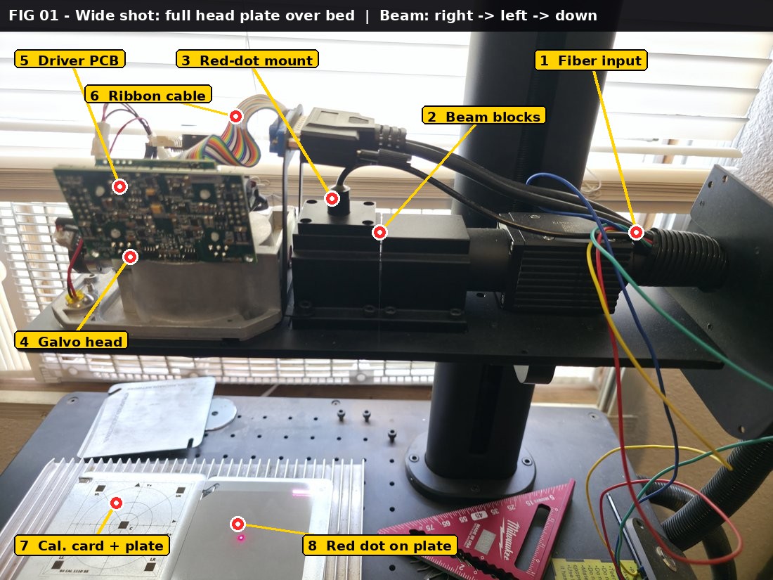
Figure 01 — Wide shot: full head plate over bed. Un-annotated original: fig01_wide-head-plate.jpg. Beam path in this view runs right to left, then down through the scan lens: (1) fiber input / laser delivery, ribbed black box and corrugated delivery on the right side of the head plate; (2) two black beam-shaping / beam-combining blocks mid-plate; (3) red-dot pointer mount on the beam block — adjust this mount for red-dot offset, nothing else; (4) silver galvo head casting on the left; (5) green driver PCB mounted on the galvo head, electronics only, no optics on the board; (6) rainbow ribbon signal cable to the JCZ controller; (7) calibration card and metal plate on the bed below, showing the calibration-card test squares; (8) red dot visible on the plate on the bed. The threaded 110 mm F-theta scan lens is on the underside of the silver galvo head and is not clearly visible in this wide photo.
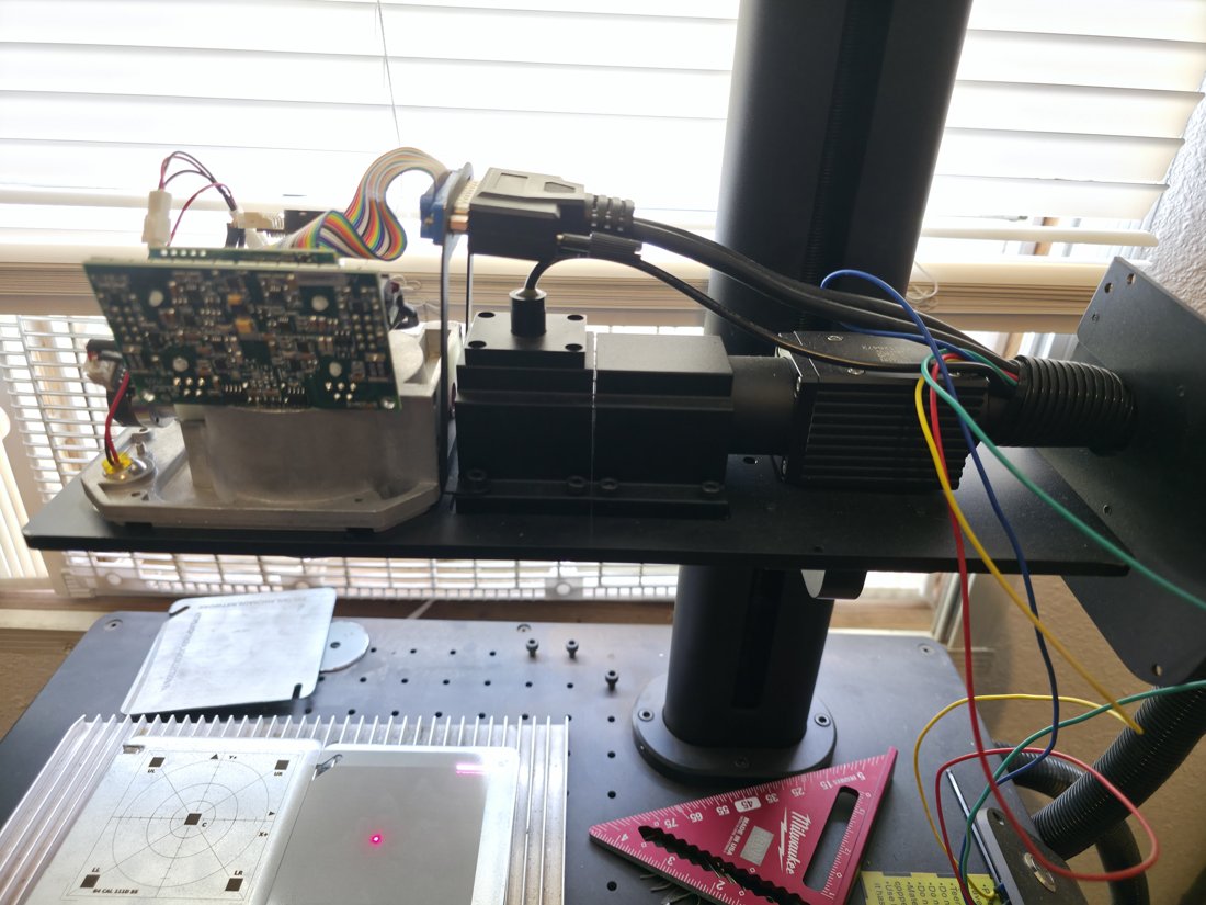
Figure 02 — ComMarker B4 red dot not aligned: red-dot pointer mount and knurled black knob close-up
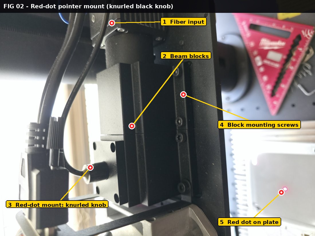
Figure 02 — Red-dot pointer mount close-up. Un-annotated original: fig02_red-dot-knob.jpg. Parts named in text: (1) fiber input / laser delivery at the top of the rotated view; (2) black beam-shaping / combining blocks in the centre; (3) red-dot pointer mount — the small knurled black knob / cylindrical mount on the lower black block; this is the mount to adjust LAST, against a real infrared test burn, when the red dot is offset from the burn; (4) beam-block mounting screws and block seating on the head plate; (5) red dot visible on the work plate below at the lower right. If framing is perfect and the red dot is ~1 mm off, adjust this red-dot mount — do not move the galvo mirrors.
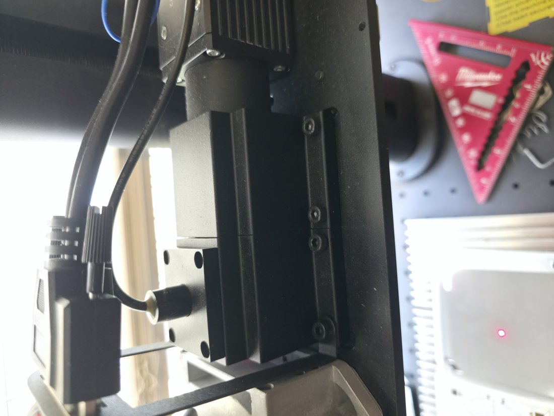
Figure 03 — ComMarker B4 galvo mirror alignment: galvo head close-up, Galvo motor A (sticker 8), white PVC block, driver PCB and ribbon cable
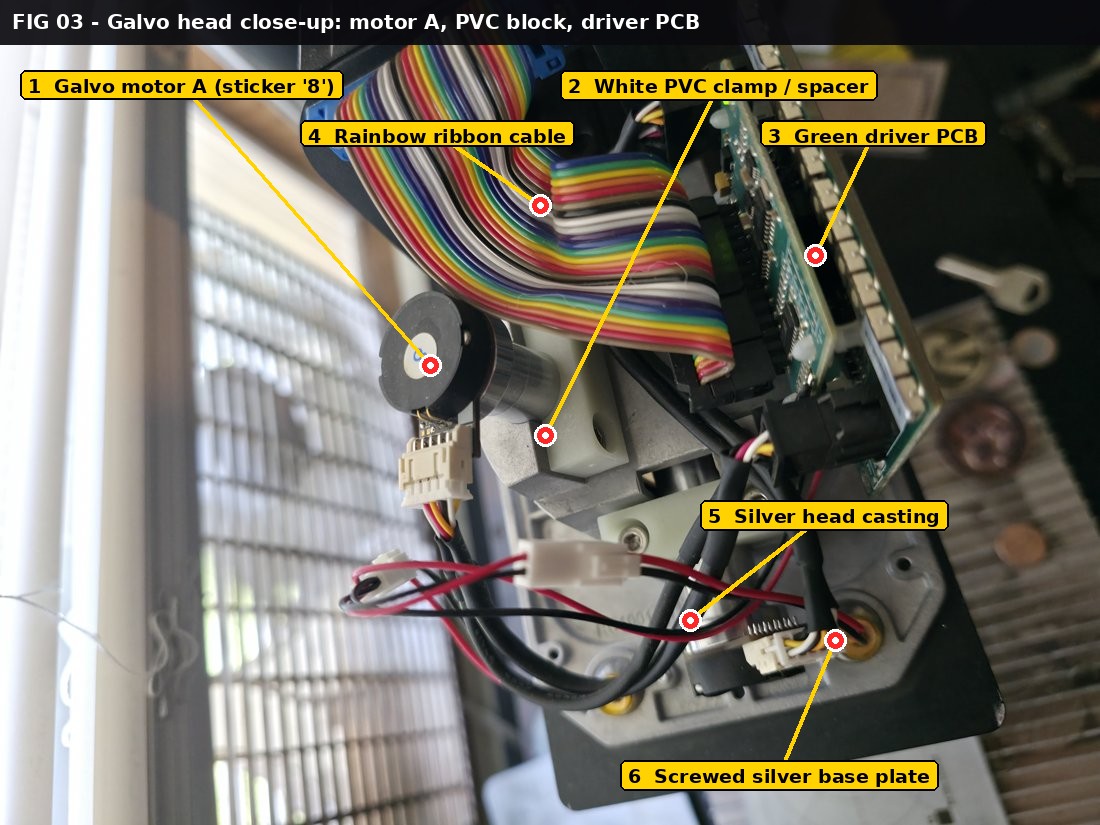
Figure 03 — Galvo head close-up. Un-annotated original: fig03_galvo-close-sticker8.jpg. Parts named in text: (1) Galvo motor A (sticker 8) — round black galvo motor cap with a white sticker "8" in a blue circle; the mirror for this motor is inside the silver head, bonded to the motor shaft, behind this cap — X or Y is unknown, do not assume; (2) white PVC / plastic block clamp and spacer holding the mirror-motor assemblies centred and square — loosening this block lets the assemblies slide in/out and tilt; (3) green driver PCB — galvo driver electronics, no optics on the board; (4) rainbow ribbon signal cable carrying signals to the JCZ controller; (5) silver galvo head casting; (6) screwed silver base plate of the galvo head, with base screws that must sit flat, square and evenly torqued.
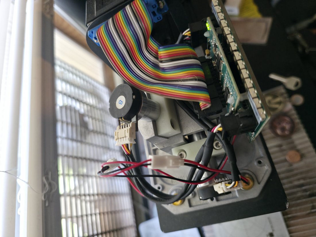
Figure 04 — Both galvo motors: Galvo motor A (sticker 8) and Galvo motor B (plain cap), X/Y still unknown
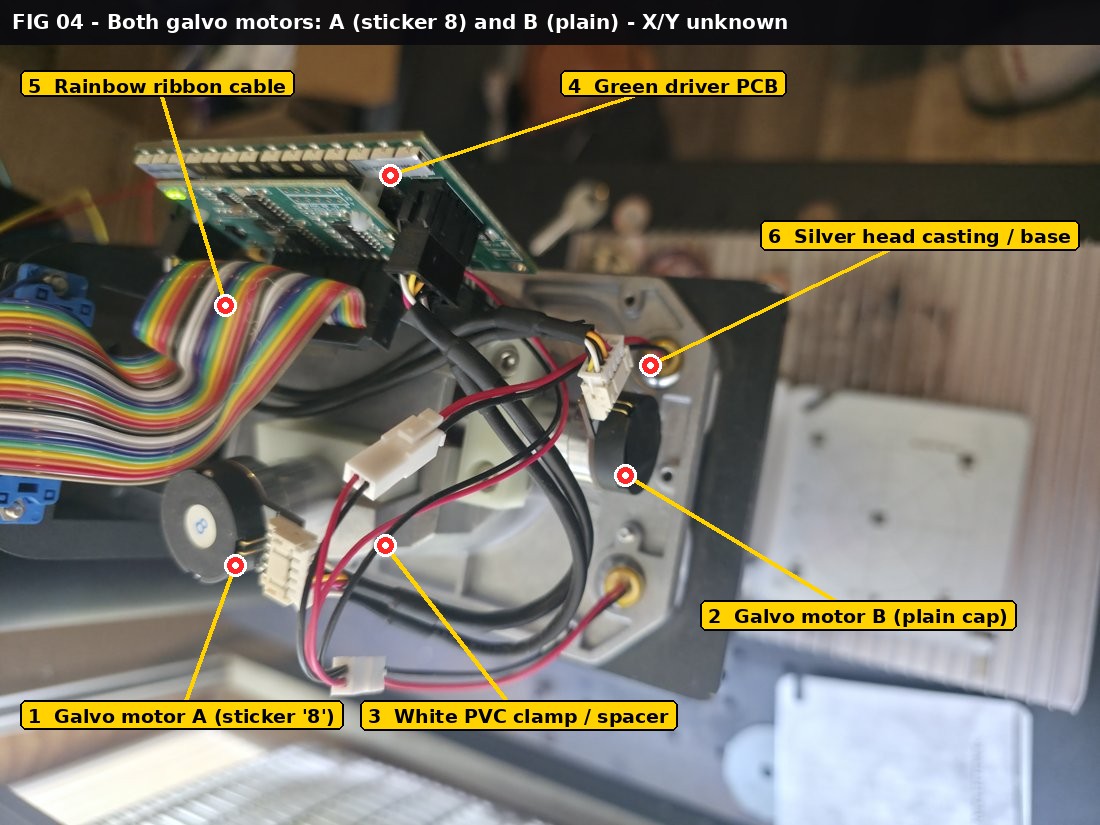
Figure 04 — Both galvo motors in one view. Un-annotated original: fig04_galvo-both-motors.jpg. Parts named in text: (1) Galvo motor A (sticker 8), round black cap with white "8" sticker, at the lower left of the head in this view; (2) Galvo motor B (plain cap), round black cap with no sticker, at the right of the head in this view; (3) white PVC block clamp/spacer holding the mirror-motor assemblies — check both assemblies are seated centred, square and at an even depth in this block; (4) green driver PCB at the top; (5) rainbow ribbon signal cable at the left; (6) silver head casting / screwed silver base plate. TODO / unknown: which physical motor, sticker "8" or plain cap, is X and which is Y in this head — to be identified from a lens-off photo, exactly as recorded in the open items. Do not relabel A or B as X or Y until that test is done.
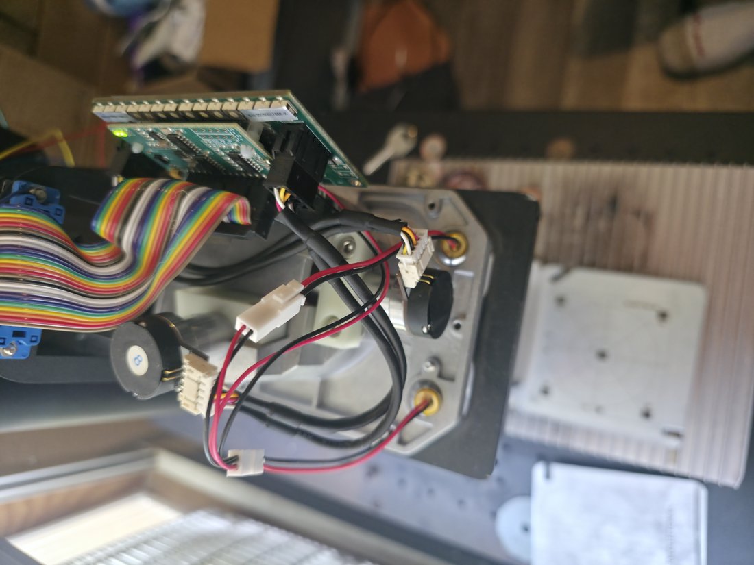
Figure 05 — Galvo head top view: both motor caps, white PVC clamp, green driver PCB, ribbon cable and calibration card
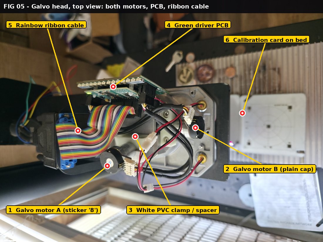
Figure 05 — Galvo head, top view. Un-annotated original: fig05_galvo-top-view.jpg. Parts named in text: (1) Galvo motor A (sticker 8); (2) Galvo motor B (plain cap); (3) white PVC clamp / spacer holding the mirror-motor assemblies; (4) green driver PCB; (5) rainbow ribbon signal cable; (6) calibration card on the bed, with centre and corner test squares used for the corner-plus-centre proof test. The mirrors themselves are inside the silver head, bonded to the motor shafts — they are not visible as loose parts in this photo and are not shift-in/out user adjustments.
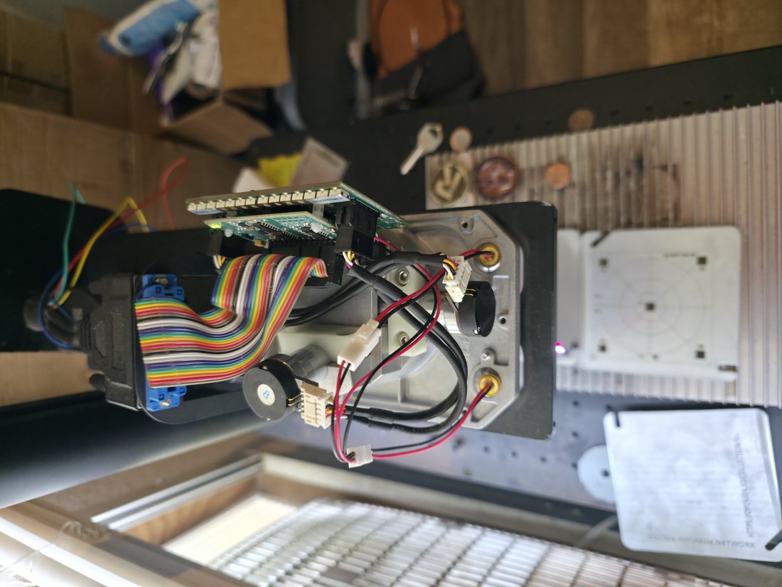
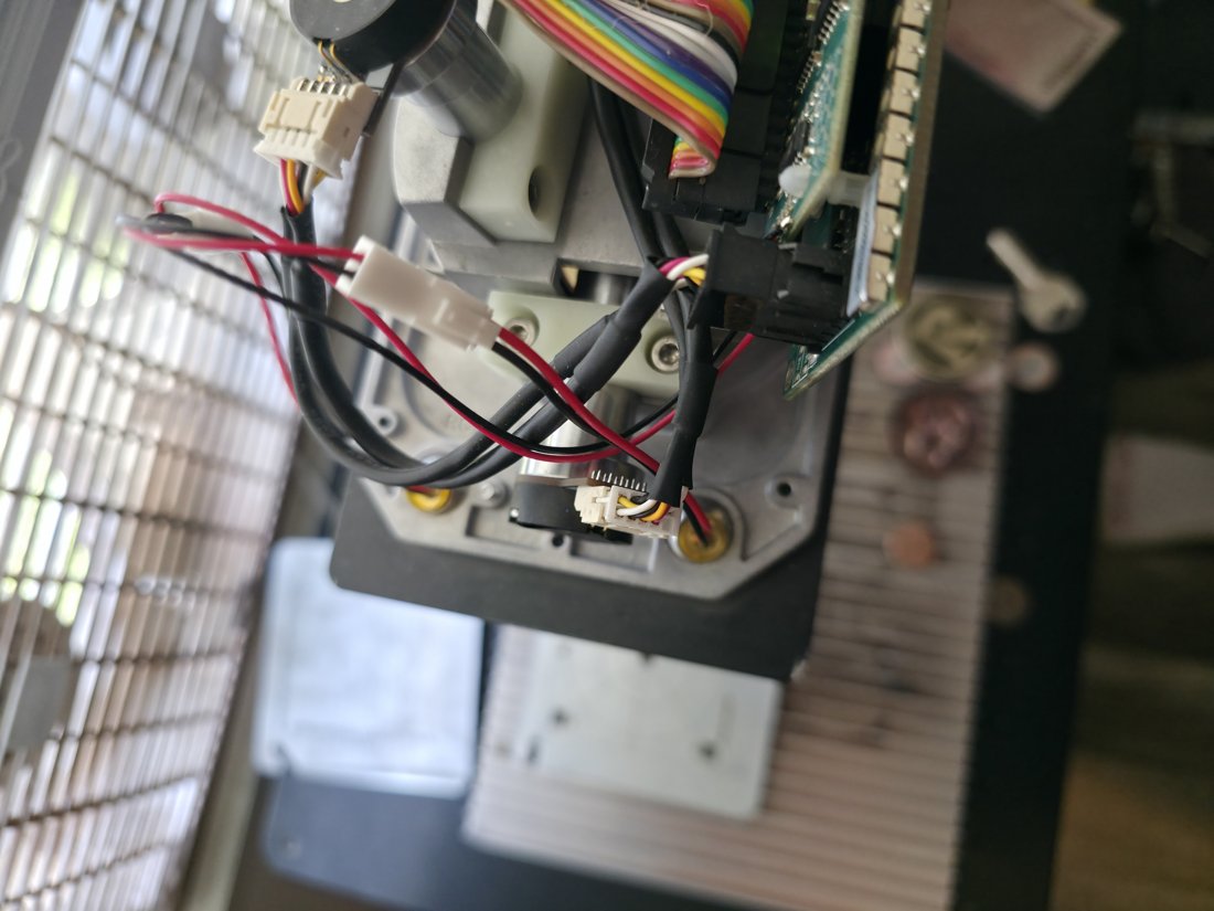
Figure 06 — Galvo head alternate close view: motor cap, PVC block, driver PCB, ribbon cable and base plate screws
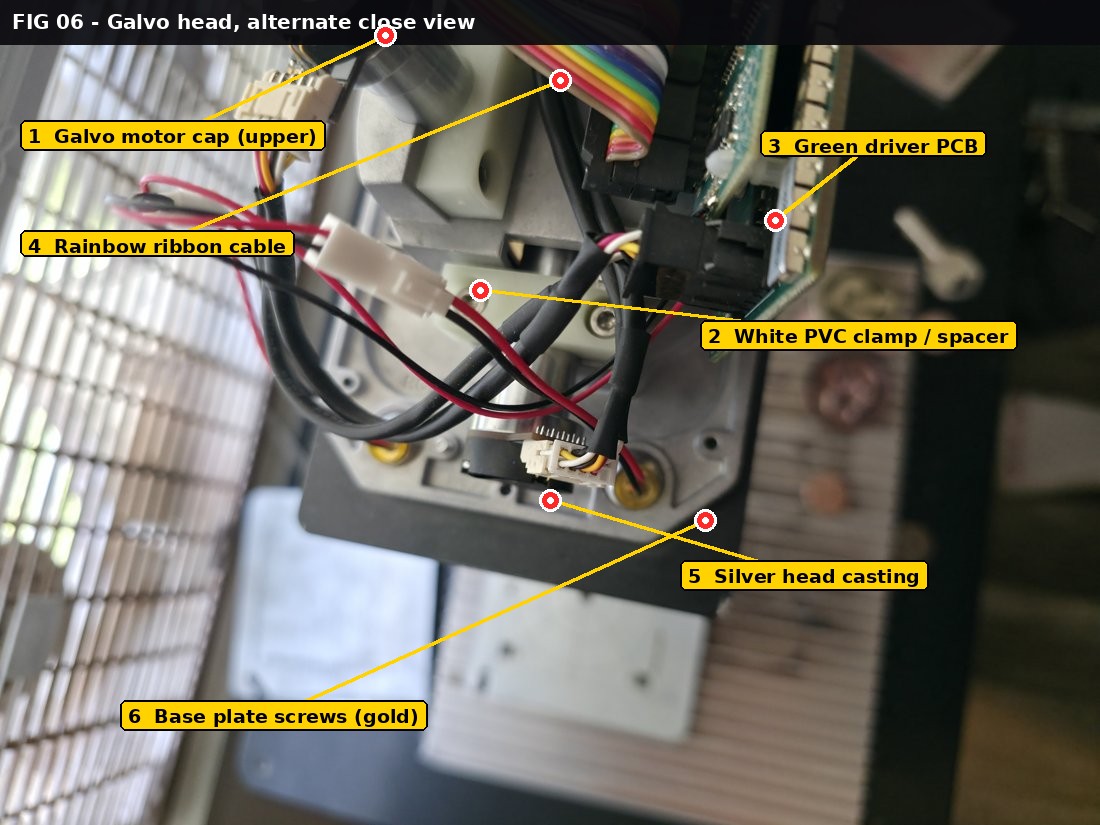
Figure 06 — Galvo head, alternate close view. Un-annotated original: fig06_galvo-alternate-close.jpg. Parts named in text: (1) galvo motor cap at the top of the frame, partly cropped in this photo — use Figures 03–05 for the clearest view of Galvo motor A (sticker 8) and Galvo motor B (plain cap); (2) white PVC clamp / spacer block; (3) green driver PCB; (4) rainbow ribbon signal cable; (5) silver head casting; (6) screwed silver base plate and its gold-coloured base screws. Wiring and white connectors in this view are motor/signal wiring to the driver electronics — no optics are on the green PCB.
What "shifting a mirror in/out" actually does
- Galvo mirrors are factory-set on their shafts; axial (in/out) position is not a user centring adjustment. Sliding an assembly in/out or tilting it in its clamp changes where the beam crosses the scan lens: beam enters off-centre, gets vignetted (clipped) on one side of the lens, focus/spot fattens toward the clipped corners. ALSO risks the mirror edge hitting its housing/travel stop (audible "clip") - possible mirror chipping.
- True user-level hardware centring points, in order of use: (a) incoming beam centring into the galvo entrance (beam-delivery/combiner block seating), (b) whole silver galvo head seating (base screws square, flat, evenly torqued), (c) mirror/motor orientation - LAST RESORT ONLY; scribe/mark exact current position first so it can be restored.
Ordered fix procedure: proof test, lens-off inspection, reseat, retest, beam blocks, red dot last
Procedure index
- Baseline proof test (BEFORE any adjustment - in progress): identical prep square in four corners + centre, one recipe everywhere (E5 prep above); photograph straight-down. Diagonal pair light = beam centration problem; one-axis gradient = single mirror/head tilt; all corners equally light = normal field falloff.
- Inspection with lens off (TODO 2026-10-18: owner removing lens, will photograph): identify which motor is X and which is Y in this head, check the clipped mirror for chips, check both assemblies' seating depth in the white PVC clamp vs an even reference.
- Reseat mirror assemblies centred + square in the white PVC block, clamp snug and even (TODO).
- Re-test with the same corner+centre squares; only then touch beam-block seating (step a) if a diagonal gradient remains.
- Red-dot: realign LAST, on its own knurled mount, against a real IR test burn - never by moving galvo mirrors.
- Re-verify software calibration (55,55 centre, jcz110.cor) after any hardware move; geometry may shift slightly once hardware is honest.
Step 1 — Baseline proof test before any adjustment
Run identical prep squares in all four corners plus the centre, one recipe everywhere (the E5 prep above on the original machine: 25% 1000 mm/s 600 kHz 10 ns, 0.01 interval, crosshatch x2). Photograph straight-down. Read the pattern before touching a screw: diagonal pair light = beam centration problem; one-axis gradient = single mirror/head tilt; all corners equally light = normal field falloff. Record the photo so every later move can be compared against this baseline.
Step 2 — Inspection with the scan lens off
With the machine fully off, support the threaded scan lens while unthreading it from underneath the silver head, set it down face-up on a clean surface, and cover it if left off. Photograph the mirrors inside the head. Identify which motor is X and which is Y in this head (still unknown — see open items), check the clipped mirror for chipped or cracked edges, and check both mirror-motor assemblies' seating depth in the white PVC clamp against an even reference. Never touch mirror faces; handle a mirror only by its mount/shaft.
Step 3 — Reseat the mirror-motor assemblies centred and square in the white PVC block
Scribe or photograph the exact starting position first so the previous state can always be restored. Reseat each mirror-motor assembly centred and square in the white PVC block clamp/spacer, then clamp snug and even. One adjustment at a time. This step addresses the accidental-displacement mechanism directly: a loosened white PVC block letting the assemblies slide in/out and tilt.
Step 4 — Retest with the same corner-plus-centre squares
Repeat the identical corner-plus-centre proof test from Step 1, same recipe, same material position, photograph straight-down. Only if a diagonal gradient remains after the reseat should you move to beam-block seating.
Step 5 — Beam-block seating, only if a diagonal gradient remains
Check incoming beam centring into the galvo entrance first (beam-delivery/combiner block seating), then whole silver galvo head seating (base screws square, flat, evenly torqued). Mirror/motor orientation remains a last resort only, with the exact current position scribed/marked first so it can be restored.
Step 6 — Red-dot realignment LAST, on its own knurled mount, against a real IR burn
Realign the red dot last, on its own knurled mount on the beam-combiner block (Figure 02), against a real infrared test burn — never by moving galvo mirrors. Target: red-dot offset under 0.5 mm from the real burn while framing remains correct.
Step 7 — Re-verify software calibration in LightBurn after any hardware move
Re-verify software calibration (LightBurn 110 mm field, centre 55,55, jcz110.cor) after any hardware move; geometry may shift slightly once hardware is honest. Confirm the 110x110 field is still centred at 55,55 and that the jcz110.cor correction still measures straight before returning to normal work.
FAQ
ComMarker B4 red dot not aligned — what do I adjust?
If the galvo framing outline is perfect but the red-dot pointer is about 1 mm from the real burn, adjust the red-dot pointer mount on the beam-combiner block (the knurled black knob in Figure 02), last, against a real infrared test burn. Do not move the galvo mirrors to centre the red dot.
ComMarker B4 galvo mirror alignment — can I shift a galvo mirror in or out to centre it?
No. The two galvo mirrors are inside the silver head, bonded to their motor shafts. Axial in/out position is not a user centring adjustment. Sliding or tilting a mirror-motor assembly in the white PVC clamp moves where the beam crosses the scan lens, causing vignetting and a fat weak spot, and risks the mirror clipping its housing. Reseat the assemblies centred and square in the white PVC block instead, one adjustment at a time, with the starting position marked.
Why does my fiber laser burn weak in corners even after software calibration?
Because software correction straightens geometry but cannot restore spot size or power density. If the beam enters the F-theta scan lens off-centre, it is vignetted toward one side of the field; the focused spot fattens and weakens in the clipped corners. That is the classic ComMarker B4 uneven engraving corners pattern: straight lines, diagonal corner falloff.
ComMarker B4 uneven engraving corners — diagonal pair light, centre solid: where do I start?
Start with the baseline proof test: identical squares in four corners plus centre, one recipe, photographed straight-down. Then inspect with the lens off, reseat the mirror-motor assemblies centred and square in the white PVC block, retest, and only then check beam-block and whole-head seating. Realign the red dot last.
Is the green PCB in the galvo head an optical part?
No. The green PCB on top of the silver head is galvo driver electronics. The rainbow ribbon is the signal cable to the JCZ controller. No optics are on the board. The only two mirrors are inside the silver head, bonded to the two galvo motor shafts.
Which galvo motor is X and which is Y on the ComMarker B4?
Unknown from the photos in this manual — this is an open item, to be identified from a lens-off photo. Until then this manual labels them only as Galvo motor A (sticker 8) and Galvo motor B (plain cap). Do not assume A is X or Y.
Index of related records
- Software calibration kit and history: /home/hank/laser/calibration/B4_CALIBRATION_KIT/ (settings backup, correction values, scans, README; scale fix X 0.9871 / Y 0.9332 era, 110 mm field centred 55,55).
- Standing operator rules: /home/hank/laser/LASER_LESSONS.md (canonical copy: https://laserview.hankelsner.tech/rules).
- Test that exposed this fault: /home/hank/laser/colortest/smalltext/grok/ (100x100 plate, 8x8 prep/index grid; E5 winner = E-column prep 25/1000/600k/10ns/0.01 xhatch x2 at 0.50 mm text, HD-black text 15/567/280k/80ns/0.003 x4 rot45).
- Photos of the head (2026-10-18 attachments): galvo head + driver board close-ups, beam blocks with red-dot knob, wide head-plate shot showing darkest calibration-card squares at bottom / left / top-right.
Open items (update as work proceeds)
- [ ] Which physical motor (sticker "8" or plain cap) is X vs Y in this head - from lens-off photo.
- [ ] Clipped mirror: chipped or clean?
- [ ] Baseline corner+centre test result recorded with photo.
- [ ] Reseat result: corner squares even? Photo.
- [ ] Red-dot offset after fix (target: under 0.5 mm).
Records checklist to update after each hardware session
- [ ] Date, machine state and LightBurn correction file in use (110 mm field, centre 55,55, jcz110.cor) recorded.
- [ ] Baseline or retest corner-plus-centre photo filed and compared straight-down against the previous photo.
- [ ] Lens-off photo filed if the lens was removed; clipped mirror noted as chipped or clean.
- [ ] White PVC clamp reseat result recorded: assemblies centred, square, clamp snug and even — photo filed.
- [ ] Beam-block or whole-head seating change recorded, one adjustment at a time, starting position scribed/photographed first.
- [ ] Red-dot offset after fix measured against a real IR burn (target: under 0.5 mm).
- [ ] Software calibration re-verified after hardware moves; any geometry shift noted.
- [ ] X/Y motor identification still marked unknown/TODO until proven from a lens-off photo — do not guess.
Thumbnail: b4_manual_thumbnail.png — ComMarker B4 — Galvo Mirror Alignment; Fix uneven corners in hardware, not software. Annotated figures: img/annot_01.jpg through img/annot_06.jpg. Un-annotated originals: img/fig01_wide-head-plate.jpg through img/fig06_galvo-alternate-close.jpg.